Iranian Classification Society Rules

< Previous | Contents | Next >
Section 24 Equipment related to Ventilation Systems in Oil Tankers
2401. General
1. Application
The requirements of this Section apply to tests and inspection for the type approval of equipment related to ventilation systems in oil tankers in accordance with the requirements in Pt 7, Ch 1, 1004. and Pt 7, Ch 6, Sec 8 of the Rules.
2. Definitions
The terms used in this Section are defined as follows:
(1) PV valve is a device designed to maintain pressure and vacuum in a closed container within preset in limit conformity.
(2) Flame screen is a device utilizing wire mesh to prevent the passage of unconfined flames in conformity.
(3) Flame arrester is a device to prevent the passage of flame by elements based on the principle of quenching in conformity.
(4) Detonation flame arrester is a device to prevent the passage of flame generated in association with a detonation in the line pipe in conformity.
(5) High velocity device is a device to prevent the passage of flame consisting of a mechanical valve which adjust the opening available for flow in accordance with the pressure at inlet of the valve in such a way that the efflux velocity can not be less than 30 in conformity.
(6) Flame speed is the speed at which a flame propagates along a pipe or the other system.
(7) Flashback is the transmission of a flame through a device.
(8) High level alarm system is a device which alarms of excessive rises in the liquid cargo level to guard liquid rising in the venting system to the height which would exceed the designed head of cargo tanks in conformity.
(9) Pressure monitoring system is a device to prevent over-pressure and or under-pressure during
cargo loading and ballasting or discharging operations, and to monitor the tank pressure and to actuate an alarm when the tank pressure reaches to a set pressure.
2402. PV Valve
1. Materials and construction
Kinds | Requirements |
Materials | (A) The device housing, and other parts or bolted used for pressure retention, shall be constructed of ma- terials suitable for the intended service and listed in a recognized national or international standard. (B) Housings, discs, spindles, seals, springs, gaskets, seals and all other integral parts, including parts with coatings to prevent corrosion, shall be made of materials resistant to attack by seawater and the liquids and vapours contained in the tank being protected. (C) Springs plated with corrosion-resistant material are not acceptable. (D) Non-metallic materials, other than gaskets and seals, shall not be used in the construction of pres- sure-retaining components of the device. (E) Resilient seals may be installed only if the device is still capable of effectively performing its func- tion when the seals are partially or completely damaged or burned. (F) Non-metallic gaskets shall be made of non-combustible material suitable for the service intended. (G) Materials for connecting pressure/vacuum valves to their respective piping systems to which they are connected. (H) The materials for all parts not identified above shall be suitable for their intended purpose. (I) The possibility of galvanic corrosion shall be considered in the selection of materials. |
Structure | (A) Device housings shall be gastight in the primary pressure zone upstream of the main valve seat to prevent the escape of vapours. |
Materials and construction of PV valve are to comply with the requirements given in Table 3.24.1 Table 3.24.1 Materials and construction of PV valve
150 Guidance for Approval of Manufacturing Process and Type Approval, Etc. 2015
![]()
![]()
Table 3.24.1 Materials and construction of PV valve (continued)
Kinds | Requirements |
Structure | (B) Housings, elements and seal gasket materials shall be capable of withstanding of the maximum and minimum pressures and temperatures to which the device may be exposed under normal operating conditions and shall be capable of withstanding the hydrostatic pressure specified in Table 3.24.2 of 2402. 2. (C) Where welded construction is used for pressure-retaining components, welded-joint design details, welding and welders shall be in accordance with the relevant Rules of Pt 2. and appropriate non-de- structive testing shall be carried out. (D) When pressure/vacuum valves are designed to allow for inspection, cleaning, repair or removal of in- ternal elements for replacement without removing the entire device form th system, the design shall not allow the valve to be incorrectly reassembled following disassembly for inspection, cleaning or repair. (E) Pressure/vacuum valves shall be designed such that condensed vapour drains from the device and does not impair the efficiency of the device. The design shall also prevent the accumulation of water inside the device and subsequent blockage due to freezing. (F) Where design does not permit complete drainage of condensed vapours through its connection to the tank, the housing shall be fitted with a plugged drain opening on the side of the atmospheric outlet of not less than 13 mm. The drain shall not allow vapour to escape unless the drain is equipped with suitable means to prevent the passage of flame and meets all requirements for efflux velocity and direction. (G) All fastenings essential to the operation of the device shall be protected against loosening. (H) Devices shall be designed and constructed to minimize the effect of fouling under normal operating conditions. The design shall be such that the device can be examined for any build-up of residue due to vapour condensation that might impair the operation of the device. (I) Devices shall be capable of operating over the full range of ambient temperatures anticipated. Devices shall also be capable of operating in freezing conditions and when covered by a layer of ice, the al- lowed thickness of which shall be stated by the manufacturer in the operating manual. Devices shall be capable of operating at whatever surface temperature is developed by heating arrangements. (J) End-of-line devices shall be constructed to direct the efflux vertically upward under all flow rates. (K) A manual means shall be provided to verify that valve lifts easily and cannot remain in the open position. (L) Valve discs shall be guided by a suitable means to prevent binding and ensure proper self-closing (seating), taking into account the possible build-up of condensed vapours passing through the valve during loading, when maintenance is carried out in accordance with the manufacturer's requirements. Valve discs shall normally close against the valve seat by metal-to-metal contact. Resilient-seating seals may be provided in the design is such that the disc closed tight against the seat in case the seals are destroyed, damaged or otherwise carried away. Valve discs may be solid or made hollow so that weight material may be added to vary the lifting pressure. If hollow discs are employed, a wa- tertight bolted cover shall be fitted to encase the weight material. The lifting pressure shall not be varied by personnel other than the manufacturer without prior ap- proval by the administration. A clear indication, visible from the outside of the valve, shall be em- ployed to indicate the position of the valve. (M)Valves may be actuated by non-metallic diaphragms except where failure would result in unrestricted flow of tank vapours to the atmosphere or in an increase in the pressure or vacuum at which the valve normally releases (N) Relief pressure adjusted mechanisms shall be permanently secured by lockwire, locknuts or other suit- able means to prevent devices from becoming misadjusted due to handling, installation or vibration. |
2. Type tests
(1) Test product
The test products used in the type test are to be of each the application.
(2) Details of tests and examinations
configuration and dimension given in
Type test and inspection of PV valve are to be in accordance with the requirements given in
Table 3.24.2
Guidance for Approval of Manufacturing Process and Type Approval, Etc. 2015 151
![]()
![]()
Table 3.24.2 Type test and inspection of PV valve
Test item | Test method |
Construction inspection | The materials, construction and dimension of the device shall be confirmed. |
Corrosion test | A corrosion test shall be conducted. In this test, a complete device, including a section of pipe sim- ilar to that to which the device will be fitted, shall be exposed to a 5 % sodium chloride solution spray at a temperature of 25℃(41℉) for a period of 240 h, and allowed to dry for 48 h. Following this exposure, all movable parts shall operate properly and there shall be no corrosion deposits that cannot be washed off. |
Hydrostatic pressure test | The pressure-retaining boundary of the device shall be subjected to a hydrostatic-pressure test of at least 150 % of maximum rated pressure(MRP) or a minimum pressure of 345 gauge (50psig), whichever is greater, for ten minutes without rupturing, leaking or showing permanent |
Performance characteristics | Performance characteristics as declared by the manufacturer, such as flow under both positive and negative pressures, operating sensitivity flow resistance and velocity, shall be demonstrated by appro- priate tests. Flow testing shall be conducted in accordance with the flow test below. |
Pneumatic test | Each finished device shall be pneumatically tested at 70 kPa either using a submersion test or a soap test for a duration of three minutes to ensure there is no leakage. |
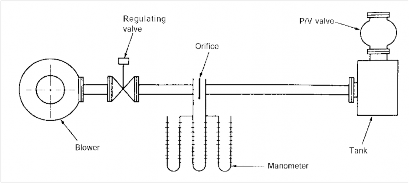
Flow tests | (a) The capacity data shall be presented in the form of curves or tables that give the volume of flow through both vacuum and pressure ports and that cover the full range between the opening pressure (or vacuum) and the pressure(or vacuum) at which the ports are fully open and the valve is flowing at its maximum anticipated rate. The capacity data for pilot-operated vents or devices that open fully at a set pressure (or vacuum) may be expressed as a flow coefficient that is the ratio of the flow through the vent to the flow through a theoretically perfect nozzle of the same diameter. Sufficient measurements shall be made a t pressures in the vicinity of the opening points, particularly at 1.1, 1.2 and 1.5 times the opening pressure and at 1.5 and 2.0 times the opening point on vacuum, to establish clearly the flow capacity at these points. (b) The capacity data shall indicate the points of initial opening and final closing of the venting device. (c) The capacity data shall be expressed in terms of cubic metres of air per hour at a temperature of 0℃ and a pressure of 1,015 hPa (d) Pressures shall be expressed in hectopascals, however, auxiliary scales shall be expressed in mil- limeters of water, and other units of measurement may also be included if desired.
Fig 3.24.1 Example of Testing Equipment for PV Valve |
2403. Devices to Prevent the Passage of Flame
1. General
(1) Materials and strength, construction and dimension, and tests and inspections of a flame screen, a flame arrester, a detonation flame arresters and a high velocity vent are to be in accordance with the requirements in the following 2 through 3.
152 Guidance for Approval of Manufacturing Process and Type Approval, Etc. 2015
![]()
![]()
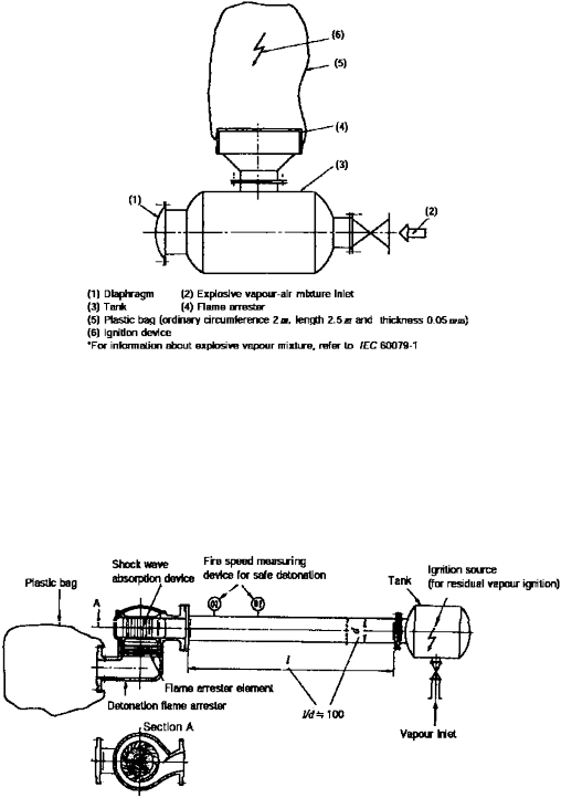
(2) For flame screens, after carrying out a corrosion test and a hydraulic test, a flashback test and a general inspection are to be carried out. The test component is not to be exchanged for each test requested and is to have the most inappropriate gap dimension expected in the service of the product. An example of testing equipment for the flashback test is shown in Fig 3.24.2.
Fig 3.24.2 Example of Testing Equipment for Flame Arrester
(3) For flame arresters, after carrying out a corrosion test and a hydraulic test, a flashback test, an endurance burning test and a general inspection are to be carried out.
(4) For detonation flame arresters, after carrying out a corrosion test and a hydraulic test, a deto-
nation test, an endurance burning test and a general inspection are to be carried out. The test component is not to be exchanged for each test requested and is to have the most inappropriate
gap dimension expected in the service of the product. An example of testing equipment
detonation test is shown in Fig 3.24.3
for the
Fig 3.24.3 Example of Testing Equipment for Detonation Flame Arrester
Guidance for Approval of Manufacturing Process and Type Approval, Etc. 2015 153
![]()
(5) For high velocity devices, after carrying out a corrosion test and a hydraulic test, a flow vol- ume test, a flashback test, an endurance burning test and a general inspection are to be carried out. The test component is not to be exchanged for each test requested and is to have the most
inappropriate gap dimension expected in the service of the product. Examples of testing
equip-
ment for the flashback test, and the flow volume test and the endurance burning test are shown in Fig 3.24.4.
Fig 3.24.4 Example of Testing Equipment for High Speed Discharger(For flashback test)
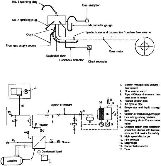
Fig 3.24.5 Example of Testing Equipment for High Speed Discharger
2. Materials and structure
Materials and structure of a flame screen, a flame arrester, a detonation flame arresters and velocity vent are to comply with the requirements given in Table 3.24.3
a high
154 Guidance for Approval of Manufacturing Process and Type Approval, Etc. 2015
![]()
Table 3.24.3 Materials and structure for devices to prevent the passage of flame
Kinds | Requirements | |
Material | (A) The casing or housing of devices should meet similar standards of strength, heat resist- ance and corrosion resistance as the pipe to which they are attached. (B) Elements, gaskets and seals should be of material resistant to both seawater and the car- goes carried. (C) The casing and element and gasket materials should be capable of withstanding the high- est pressure and temperature to which the device may be exposed under both normal and specified fire test conditions. | |
Structure | General | (a) The design of devices should allow for ease of inspection and removal of internal ele- ments for replacement, cleaning or repair. (b) Devices should allow for efficient drainage of moisture without impairing their efficiency to prevent the passage of flame. (c) Fastenings essential to the operation of the device, i.e. screws, etc., should be protected against loosening. (d) Devices should be designed and constructed to minimize the effect of fouling under nor- mal operating conditions. (e) All flat joints of the housing should be machined true and should provide for a joint having an adequate metal-to-metal contact. (f) Resilient seals may be installed only if their design is such that if the seals are partially or completely damaged or burned, the device is still capable of effectively preventing the passage of flame. (g) End-of-line devices should be so constructed as to direct the efflux vertically upwards. (h) Devices should be capable of operating in freezing conditions. (i) Devices are to be protected against mechanical damage. (j) Performance characteristics, such as the flow rates under both positive and negative pres- sure, operating sensitivity, flow resistance and velocity should be demonstrated by appro- priate tests. In this case, the presence of the Surveyor may be dispensed with. |
Flame screen, flame arrester and detonation flame arrester | (a) The design of devices should allow for ease of inspection and removal of internal ele- ments for replacement, cleaning or repair. (b) The clear area through the element is to be at least 1.5 times the cross-sectional area of the line. (c) The elements are to be secured in the casing in such a way that flame cannot pass be- tween the element and casing. | |
High velocity devices | (a) High velocity devices are to have a width of the contact area of the valve seat of at least 5 mm. (b) Means should be provided to check that any valve lifts easily without remaining in the open position. (c) In the case of high velocity vents, the possibility of inadvertent detrimental hammering. | |
3. Type tests
(1) Test product
The test products used in the type test are to be of each configuration and dimension given in the application.
(2) Details of test and examinations
Type test and inspection of a flame screen, a flame arrester, a detonation flame arresters and a high velocity vent are to be in accordance with the requirements given in Table 3.24.4
Guidance for Approval of Manufacturing Process and Type Approval, Etc. 2015 155
![]()
![]()
Table 3.24.4 Type test and inspection for devices to prevent the passage of flame
Kind | Test item | Test method |
1. General | (a) The following characteristics should be recorded, as appropriate, throughout the tests: (i) concentration of fuel in the gas mixture (ii) temperature of the test gas mixture at inflow of the device (iii) flow rates of the test gas mixtures when applicable. (b) Flame passage should be observed by recording, e.g., temperature, pressure, or light emission by suitable sensors on the protected side of the device; alternatively, flame passage may be recorded on video tape. (c) If any device is provided with heating arrangements so that its surface temperature ex- ceeds 85℃, then it should be tested in accordance with 2 through 6 of this Table at the highest operating temperature. (d) End of line devices which are intended for exclusive use at openings of inerted cargo tanks which are appropriate with the requirements of Pt 7, Ch 1, Sec 11 of the Rules need not be tested against endurance burning In this case, flashback may be dis- pensed with. (e) For ships other than those, 500 GT or above, engaged in the international voyages, the continuous combustion test for flame arrests, the flash back test and the continuous combustion test for high velocity devices may be omitted. (f) After the relevant tests, the device should not show mechanical damage that affects its original performance. | |
2. Flame ar- resters lo- cated at openings to the atmosphere. | General | The test rig should consist of an apparatus producing an explosive mixture, a small tank with a diaphragm, a flanged prototype of the flame arrester, a plastic bag and a firing source in three positions. Where end-of-line devices are fitted with cowls, weather hoods and deflectors, etc., these attachments should be fitted for the tests. |
Flashback test | (i) The tank, flame arrester assembly and the plastic bag enveloping the prototype flame arrester should be filled so that this volume contains the most easily ignitable pro- pane/air mixture. However, devices are to be tested with ethylene or test media with MESG not more than 0.65mm for Apparatus Group IIB on chemical tankers and with hydrogen or test media with MESG not more than 0.28mm for Apparatus Group IIC on chemical tankers, according to the apparatus group assigned as per column i'' of the Annex 7B-1 Table of Summary of Minimum Requirements of the Guidance Pt 7 Ch 6. (ii) Three ignition sources should be installed along the axis of the bag, one close to the flame arrester, another as far away as possible therefrom, and the third at the midpoint between these two. (iii) These three sources should be fired in succession, twice in each of the three positions. (iv) Devices should not be capable of being bypassed or blocked open unless they are test- ed in the bypassed or blocked open position. (v) The temperature of the test gas should be within the range of 15℃ to 40℃. | |
Endurance burning test | Following tests are to be carried out to ascertain that no flashback occurs. (i) Without the plastic bag the flame arrester is to be so installed that the mixture emission is vertical. (ii) Endurance burning is to be achieved by using the most easily ignitable gasoline va- pour/air mixture with the aid of a continuously operated pilot flame. (iii) By varying the flow rate, the flame arrester is to be heated until the highest obtain- able temperature on the cargo tank side is reached. This temperature is to be main- tained for a period of 10 minutes, after which the flow is to be stopped and the con- ditions are to be observed. The highest obtainable temperature may be considered to have been reached when the rate rise of temperature does not exceed 0.5℃ per minute over a ten-minute period. If difficulty a rises in establishing stationary temperature conditions (at elevated tem- peratures), endurance burning, by using the flow rate which produced the maximum temperature during the foregoing test sequence, is to be continued for a period of two hours from the time the above mentioned flow rate has been established. | |
3. Tests for flame arresters located in-line | General | The following tests are to be carried out to ascertain that no flashback occurs. In these tests, the flame arrester is to be tested with the inclusion of all pipes, tees, bends, cowls, weather hoods, etc. which may be fitted between the device and atmosphere. |
Flashback test | A flashback test is to be carried out in accordance with 2. of this Table. In this test, the plastic bag is to be fitted at the outlet to atmosphere. | |
Endurance burning test | An endurance burning test is to be carried out in accordance with 2. of this Table. In this test, the flame arrester is to be so installed as to reflect its final orientation. | |
156 Guidance for Approval of Manufacturing Process and Type Approval, Etc. 2015
![]()
![]()
Table 3.24.4 Type test and inspection for devices to prevent the passage of flame (continued)
Kind | Test item | Test method |
4. Tests for detonation flame arrest- ers located in-line | General | The following tests are to be carried out using the test apparatus which consists of an ap- paratus producing an explosive mixture, a tank, a plastic bag, a pipe of suitable length and of the same diameter as the flange of the detonation flame arrester, ignition device and a measuring instrument of flame speed , and it is to be ascertained that no flashback occurs and no part of the flame arrester is damaged or shows permanent deformation. |
Detonation test | (i) A detonation flame arrester is to be installed at one end of a pipe, and a plastic bag is to be affixed on the other end of the detonation flame arrester. (ii) The tank, the plastic bag, the pipes and the detonation flame arrester are to be filled with the most easily ignitable propane/air mixture. However, devices are to be tested with ethylene or test media with MESG not more than 0.65mm for Apparatus Group IIB on chemical tankers and with hydrogen or test media with MESG not more than 0.28mm for Apparatus Group IIC on chemical tankers, according to the apparatus group assigned as per column i'' of the Annex 7B-1 Table of Summary of Minimum Requirements of the Guidance Pt 7 Ch 6. (iii) They are to be ignited in the tank and three detonation tests are to be carried out. The velocity of the flame measured near the detonation flame arrester is to have a value of that for stable detonations. | |
Endurance burning test | In case where the distance requirement in the endurance burning test, 3. of this Table cannot be met, an endurance burning test is to be carried out in addition to the require- ments in the detonation test. | |
5. Tests for flame screens | Flashback test | A flashback test is to be carried out in accordance with 2. or 3. of this Table depending on the installed position of the flame screen. |
6. Tests for high velocity devices | Flow condition test | A flow condition test is to be carried out with high velocity vents using compressed air or gas at agreed flow rates, and the following is to be measured and recorded. (i) The flow rate. Where air or gas other than vapours of cargoes with which the vent is to be used is employed in the test, the flow rates achieved are to be corrected to re- flect the vapour density of such cargoes. (ii) The pressure before the vent opens. The pressure in the test tank on which the device is located is not to rise at a rate greater than 10 kPa/m in. (iii) The pressure at which the vent opens. (iv) The pressure at which the vent closes. (v) The efflux velocity at the outlet which is not to be less than 30m/s at any time when the valve is open. |
Flashback test | The following tests are to be carried out using the test apparatus producing explosive mix- ture, flowmeter, ignition device and diaphragm, and it is to be ascertained that no flash- back occurs. (i) The test rig and the high velocity device are filled with the most easily ignitable gaso- line vapour, hexane vapour or propane/air mixture. The mixture is to be ignited with the aid of a permanent pilot flame at the outlet. A flashback test is to be carried out with the device in the upright position and then inclined at 10° from the vertical. For some device designs further tests with the device inclined in more than one direction may be necessary. (ii) In each of these tests specified in (i), the flow is to be reduced until the device closes and the flame is extinguished, and each is to be carried out at least 50 times. | |
Endurance burning test | The following tests are to be carried out using the test apparatus producing explosive mix- ture, blower, tank with a diaphragm, safety device and flowmeter, and it is to be ascer- tained that is no flashback occurs. (i) An endurance burning test is to be carried out in accordance with 2. of this Table. (ii) Following the test specified in (a), the main flame is to be extinguished and then, with the pilot flame burning or the spark igniter discharging, small quantity of the most easily ignitable mixture is to be allowed to e scape for a period of 10 minutes main- taining a pressure below the value of 90 % of the valves opening setting. (iii) For the purpose of this test, soft seals and seats a re to be removed. | |
7. Corrosion test | A corrosion test is to be carried out. In this test a complete device including a section of the pipe to which the device may be fitted is to be exposed to a 5 % sodium chloride sol- ution spray at a temperature of 25℃ for a period o f 240 hours, and allowed to dry for 48 hours. Following the test all movable parts are to operate properly and there is to be no corrosion deposits which cannot be washed out. This test is to be carried out before carrying out the tests specified in 2. through 6 of this Table. | |
Guidance for Approval of Manufacturing Process and Type Approval, Etc. 2015 157
![]()
![]()
Table 3.24.4 Type test and inspection for devices to prevent the passage of flame (continued)
Kind | Test item | Test method |
8. Hydraulic test | For the casing of a device, a hydraulic test at the same test pressure as the pipe to which the device is attached. This test is to be carried out before carrying out the tests specified in 2. through 6 of this Table. (a) End of line device of all sizes : 90 kPa (b) In-line device up to 200 mm pipe diameter : 1,500 kPa (c) In-line device above 200 mm and up to 300mm : 1,800 kPa (d) In-line device above 300 mm pipe diameter : to the satisfaction of the Society | |
9. Finished condition in- spection | The materials, construction and dimensions of the device are to be ascertained. | |
2404. High level alarms
Performance, construction, tests and inspections of a high level alarm are to be requirements given in Table 3.24.5.
in accordance with
Table 3.24.5 Performance, construction, tests and inspections of a high level alarm
Item | Requirements |
Performance and construction | (A) The deviation between the indicated level and the actual one is to be within 25mm or less. (B) The liquid level can be indicated within a time lag of 3 seconds following the actual liquid lev- el fluctuation. (C) The device is to be capable of withstanding motions, vibrations and inclinations of a ship. (D) Electrical installations of the device are to comply with the requirements in relevant Rules. (E) Due consideration is to be paid against the generation of static electricity. (F) The device is to be capable of withstanding the highest pressure and temperature to which the device may be exposed under normal condition, and is to be of material resistant both sea wa- ter and cargoes carried. (G) The construction of a device is to be in accordance with the following requirements: (a) The design is to allow for ease of repair. (b) The fastenings a re to be protected against loosening. (H) The operational error is to be demonstrated by an appropriate test. (I) The alarms are to be visible and audible, and to be capable of identifying the tank in which the liquid level rises. (J) The audible alarm is to be capable of being stopped manually. |
Type tests | High level alarms are to comply with the requirements specified in 2303. of this Guidance. |
2405. Pressure monitoring system
Construction, strength, test and inspections of a pressure monitoring system are to be in accordance with the requirements given in Table 3.24.6.
Table 3.24.6 Construction, strength, test and inspections of a pressure monitoring system
Item | Requirements |
Performance and construction | (A) A pressure monitoring system is to comply with the requirements specified in 2302. (B) In addition to the requirements specified in (A), a pressure monitoring system is to be in ac- cordance with followings: (a) The alarms are to be visible and audible, and to be capable of identifying the tank which is the condition of over-pressure or under-pressure. (b) The audible alarm is to be capable of being stopped manually. |
Type tests | (A) The details of tests are to be in accordance with the requirements specified in 2303. (B) In addition to the requirements specified in (A), a pressure monitoring system is to be in ac- cordance with followings: (a) The operational errors are to be in ranges from 0 % to -10 % of the set pressure on the pres- sure side and from +10 % to 0 % of the set pressure on the vacuum side. (b) The pressure can be measured within a time lag of 3 seconds following the actual pressure fluctuation. |
158 Guidance for Approval of Manufacturing Process and Type Approval, Etc. 2015
![]()
![]()